
Learning to Use an Optocoupler or Optoisolator
An optocouplter or optoisolator is a cool little device that allows you to completely separate sections of an electrical circuit. From what I understand, the MIDI protocol requires the use of optocouplers in all devices. I want to use an optocoupler for separating a circuit powered by USB (5V) from one powered by a 7.2V RC Car battery. The idea behind this is that I want to protect the USB based circuit(and my computer) from the large amperages, inductance, higher voltages and other things going on in the RC Car side of the circuit, but still want to be able to control it using a USB device. I am writing this after successfully using a Fairchild 4N25 Optocoupler to deliver pulse width modulation from a USB based circuit to the 7.2V circuit in order to control a servo.
The following are a series of descriptions of ideas that I have learned while working with an optocoupler over the last month.
1. Dont waste your time making or purchasing a breakout board for a package size that is large enough to directly solder wires to.
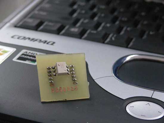
The leads are far enough apart. This didnt need a breakout board made for it.
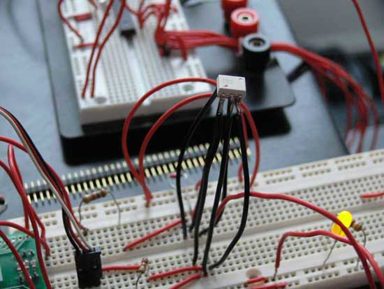
This is the way I should have done it in the first place
The Fairchild 4N25SM has large enough pin spacing despite being surface mount, that you can easily solder wires directly to the pins for experimentation. I made a breakout board for this part and after a week found out the that optocoupler was not preforming as it should have. I think I got the pins on the optocoupler too hot while soldering them to the breakout board.
2. I'm not sure about other optocouplers, but the 4N25 works on the major principal of sinking current.
Before actually working with the part, I did not understand that you have to configure the optocoupler in such a way that when the signal you are trying to reproduce goes low, the optocoupler should turn ON.
This is echoed in Paul Hill's Speed Control Examples Using the 4N25 as well as the
test diagram that is shown in the Fairchild datasheet:
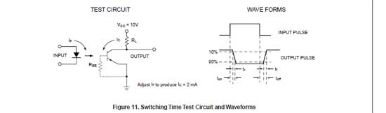
See how the output is the inverse of the input according to the diagram on the right?
In all of the configurations of the 4N25 I have always seen output tied in paralell to the transistor sides collector(pin 5). The transistor side of the 4N25(pin 4, 5, and 6) reproduces a signal by always being high except for when the LED gets turned on. When the LED in the 4N25 turns on, it causes the
3. Pin 6 (the base of the transistor) is used to tweak the sensitivity of the optocoupler.
When doing research for working with the 4N25 I always saw diagrams of the base not being connected at all, or being connected to ground by a very large resistor in the 100k and above range. Initially I did not connect pin 6, the base to anything.
However, after sending a pulse width modulation signal through the optocoupler to control a servo, I noticed the servo would not hold its position without rapidly jerking a small amount back and forth. I tested the output of the optocoupler with two servos and noticed the same behavior.
I then hooked a large range potentiometer between the base of the transistor(pin 6) and ground. As I ran the resistance on the base of the transistor from zero to around 80K ohms, I could visibly see the jerking motion on the servo increase and decrease to smooth operation.
4. A simple test setup for an optocoupler can be constructed using a single power source, LED, resistors, and a pushbutton switch.
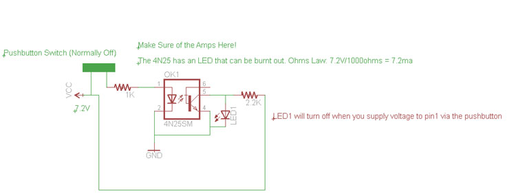
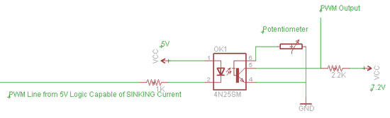
The final diagram of the configuration I am currently using to smoothly control a servo as of writing this can be seen below:
Comments

Optocouplers can be used as either input or output devices. They can have additional functions such as intensification of a signal or Schmitt triggering (the output of a Schmitt trigger is either 0 or 1 - it changes slow rising and falling waveforms into definite low or high values). Optocouplers come as a single unit or in groups of two or more in one casing.
Read more: http://romux.com/tutorials/pic-tutorial/optocouplers#ixzz42DjrPqb7

How to eliminate the effect of TV remote control from from IR photocoupler?
Can you tell me where the base of the optocoupler connected?Also I wanna connect a source/sink to it.Does that go to the collector?
Thanks, cleared up a similar situation with a high voltage opto-isolator from Maplin.co.uk

I want to connect optoisolator in a protection circuit where if i give 60v input from solar which will be scaled down to 7V but this 7V cant be constant since my input is changing, so i need it to change correspondingly with the input. is that possible using this optoisolator? please help me understand this
Thanks :)
Dear, Thx for the Pot. but i my output is highly disturbed at the operating frequency of 100 kHz..

how to connect this ic (optocoupler) to a simple calculator?

Your description of what to do with the 100k resistor, helped me out of problems. Strange enough, on my breadboard try out I had to *remove* this R to make it work.
Anyway thanks man.
Hi guys!
Please help me to use mct2e

i dont think it is working.... i have worst experience abt the ckt
Hi abhishek,
In this example the pulse is being generated on the cathode (2). The pulse is created by sinking the cathode to ground through a microcontroller.
It has been a while but I think the output is coming from the collector.
The whole thing is confusing to look at because both sides are creating an oscillation by sinking current. On the right side, the PWM output happens because the path on pin 4 opens up and current flows to ground when the LED is lit on the left side.

hi
how am i supposed to connect a pulse to mct2e and from which i have to take the output .i mean to which pins i have to connect .
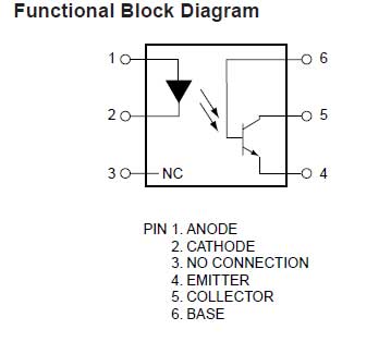
pins
1-anode
2-cathode
3-no internal connection
4-emitter
5-base
6-collecter
so to which pin i have to give pulse nd from which i have to take the output
Can an opto isolator be used with a pic 12F683 output (pin5 ! The voltage at the pin is > < 2.5v. I want it to switch ON a 2n3904 transistor.
Adopting to finite voltages like .2v and 1.6v will depend on the datasheet of your specific optocoupler and other external components you use to manipulate those values.
Think of the optocoupler like a transistor and an LED. All LED's have different threshold voltages to turn them on and off completely while not damaging them.
Likewise, all transistors have certain threshold conditions depending on their types and models to activate or deactivate them.
In all cases, these conditions can be manipulated by using external components if the optocoupler doesn't fit the design exactly.
As usual there is no straightforward yes or no answer to your question. Best advice I have is to read the datasheet, do calculations more than once, then test.

will optocoupler sense the difference between .2V n 1.6V .. should be off @ .2V n work by 1.6v
niceee
Thank you, boy!!! It helps a lot!

Have you found one that can be used to pass analog signals? I want to make a protection circuit for my signal generator.
Hi saadhana,
An opto isolator is just another name for an optocoupler.
These devices work very similar to a transistor in a circuit except they provide complete electrical isolation between the two sides of the circuit you implement them in.
Common use cases for them are providing signaling across different voltages, or in interface bus designs such as MIDI where engineers wish to protect the circuit and external devices from potential outside damage.
what is meant by opto isolator? how it works in circuit?
can u give me any example?....
Arjoon,
I'm not sure. It would depend on several factors concerning your design.
if i use an astable oscillator. what will be the maximum operating frequency
hey guy plz help me to use 4N32 opto
i need it immediatly plzzz guyzzzzz
Muslem,
If you don't have enough amperage/voltage available to actually turn on the LED inside the optocoupler, you may have issues.
The first 4N25 that I fooled with was broken. You should be able to tell my doing continuity tests between the different legs of the transistor.
Is it also possible that your switching speed for your application is too high to notice much of a change?
Hi,
In the same optocoupler i give input pulse but I do n't get any output. wheter o or 1. whats the problm? Can any one response me ?
Thanks to all

Hi Joi. I don't remember exactly what the resistance value of the potentiometer was. I know the pot that I used has a range up to 70,000Ohms.
Hi! I'm doing exactly the same thing. My servo also has this jitter. Do you know approx. how big your bias resistor is in ohms? I'd like to decrease board size by just having a fixed resistor instead of a pot.. :) Thanks in advance, Joi
Thanks Albie. Your exactly right. I crossed out what I had and changed it to output.
In the last line of paragraph 2, I think you might mean "output" instead of "input". The output would go low when it turns on causing the transistor to sink current.
Comments are currently disabled.
